We can basically differ between two types of iLLDs:
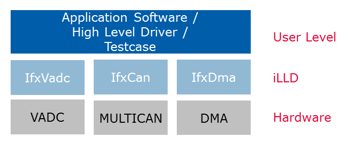
Unifunctional Peripheral Drivers
Unifunctional peripheral drivers are simple modules where the target peripheral is able to carry out one type of functionality.
Example: VADC peripheral for analog-to-digital conversion. Multican for CAN protocol communication, DMA for DMA functionality, etc.
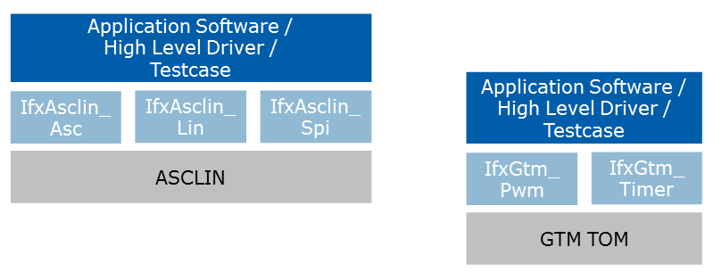
Multifunctional Peripheral Drivers
These kind of peripheral drivers are complex to handle, and here the target peripheral can carry out multiple functionalities ("use cases").
Example: AscLin peripheral can be configured as a common UART, but also as a LIN or even a SPI.
GTM TOM/ATOM can be used as PWM generator, complex waveform generator and any generic timer, etc.
Content of Peripheral Drivers
iLLDs consist of following components:
- Peripheral Register Memory Map (SFR header file)
- a Standard Layer with (verbose) access functions to SFRs which are changed during application runtime
- an Interface Layer with configuration and handling functions
Multiple Interface Layers could be available if the peripheral is used for different purposes. - Pinmaps to configure I/O multiplexers
Configuration Data Structures
A configuration structure, which is part of an interface layer, holds the parameters to configure the driver. Depending on the iLLD and its associated peripheral there could be multiple levels of configuration data structures. As in case of VADC there could be data structure to configure the VADC module, a structure for the configuring the group and another for the channels.
The data structure shall be defined in a memory optimised way considering the structures are non-packed in the memory map. All the structure elements shall be organised in a way that they are ordered in the descending order of their physical memory size.
Usage: In normal cases configuration data structures are locally stored (on the stack) inside specific initialization routines. They can also be placed in the flash/ROM
Example for a configuration struct:
Runtime Variables (Handles)
Runtime variables are usually stored in so called "handles". This structure is separated from the configuration structure mentioned above (because such structures are only needed during initialization phase).
Handles are used to reference resources of a peripheral by interface functions without unnecessary calculation or parameter passing overhead. A handle struct contains at least a pointer to the base address of the peripheral which should be accessed, pointers to peripheral subcomponents where required, and/or indices (such as a channel or timer number).
Handles are to be instantiated per instance of the used peripheral. Higher SW layers store knows number of instances required for the intended application and it reserves the memory for these many data structures.
The data structure must be made to be available in the DMI RAM of the Cpu from which lld API calls are more frequently done.
Example for an handle: