|
This driver implements the timer functionalities as defined by Standard interface: Timer. The user is free to use either the driver specific APIs below or to used the standard interface APIs.
Specific Implementation
The timer fucntinality is implemented using either a single or 2 TOM channels. The dicision to use 1 or 2 channels is done depending on the following requirements:
- relative position of the timer channel to the other channels used if any
- need to trigger an other module, for example ADC triggering.
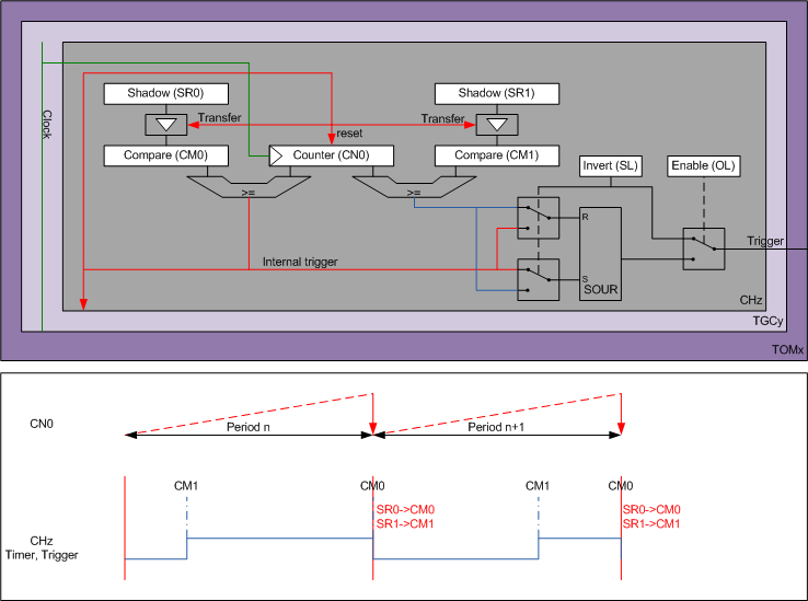
The figure below show how the TOM is configured when a single TOM channel is used for the timer and trigger functinalities. The internal trigger signal (red line) is generated when the counter CN0 reach the CM0 compare register. The value of CM0 act as the period value. This internal trigger is used to reset the CN0 counter and simultaneously transfer the shadow values for the period value (SR0->CM0) and trigger edge (SR1->CM1). The internal trigger is used as a trigger input to the next TOM channel. The trigger signal (output trigger) is generated by the CM0 and CM1 compare values. Depending on the trigger signal active edge configuiration, the CM0 will reset, and the CM1 will set the trigger signal, or vice versa.
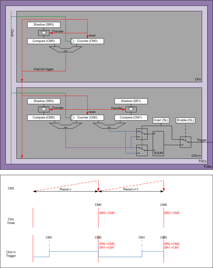
In case 2 TOM channels are used for the timer and trigger functionalities, the 1st channel (CHz in the figure below) is used for the generation of the period, and the 2nd channel (CHz+n the below figure, the figure shows n=1 as example) is used for the trigger generation.
The CHz TOM channel generates the internal trigger signal (red line) when the counter CN0 reach the CM0 compare register. The value of CM0 of CHz act as the period value. This internal trigger is used to reset the CN0 counter and simultaneously transfer the shadow period value (SR0->CM0). The internal trigger is used as an input for the next TOM channel.
The CHz+n TOM channel, uses the internal trigger signal to simultaneously resets the counter CN0, and transfer the shadow values used for the generation of the trigger falling and rising edges (SR0->CM0 and SR1->CM1). The internal trigger is used as a trigger input to the next TOM channel. Depending on the trigger signal active edge configuiration, the CM0 will reset, and the CM1 will set the trigger signal, or vice versa. In orter to have a similar behaviour to the single channel implementation, the CM0 is set to the same value as CHz CM0, and CM1 is used for the trigger edge.
In order to ensure a coherent update of all registers, the internal trigger must be disable before updating the timer and trigger shadow values, and enabled once the update is done. The transfer will ocucrs at the next timer reset.
- Resources used:
- if the trigger channel is identical to the timer channel, only one TOM channels is used
- if the trigger channel is different from the timer channel, 2 TOM channels are used
- All channels used must be own by the same TOM and TOM TGC
- The timer counting direction is limited to IfxStdIf_Timer_CountDir_up
- If the TOM trigger channel is not the same as the TOM timer channels
- The TOM channel used for the trigger must have a lower index than the TOM channels used for the timer.
- the TOM channels must be contiguous, unless specified by the driver using the timer driver.
Note: the timer and trigger must bepart of the same TGC, but PWM channels can be of different TGC of the same TOM as the timer
For a detailed configuration of the microcontroller, see IfxGtm_Tom_Timer_init().
Usage example
Initialisation:
During run-time, the interface functions should be used: