|
This driver implements the PWM functionalities as defined by Standard interface: Multi-channels, dual-complementary PWM interface. The user is free to use either the driver specific APIs below or to used the standard interface APIs.
Specific Implementation
The PWM driver is a concatenation of a timer with additional PWM generation cells.
The timer is implemented as described in TOM Timer Interface Driver, it generate an internal trigger that is used to synchronize all the TOM channel used (shown in red in the pictures below).
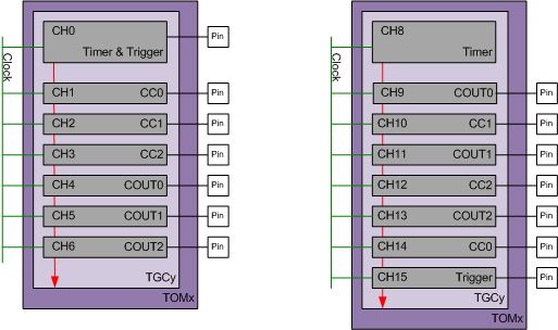
The picture below presents two configuration examples:
- On the left, the timer and trigger are generated using the same TOM channel CH0. The 3 dual-complementary PWMs, CCx and COUTx, are generated using 6 additional TOM channels (CH1 to Ch6).
- On the right, the timer and the trigger uses separate TOM channels to allow the triggering of the ADC conversions. The order of the CCx and COUTx has been allocated freely between CH9 up to CH14.
Each of the TOM channel used for the generation of the CCx and COUTx signals are configured as in the figure below:
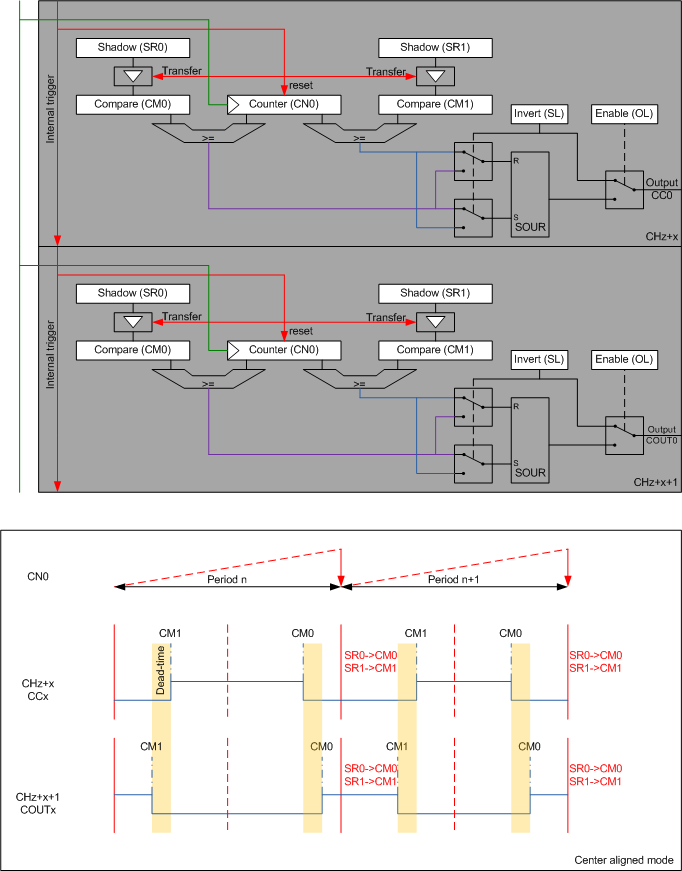
.
The internal trigger (red line) is generated by the timer on timer rest and used by the TOM PWM channels to reset the counters CN0 and transfer the shadow values saved in SR0 and SR1 to the CM0 and CM1 registers. When the counter CN0 reach the values of the CM0 or CM1 compare registers, a rising or falling edge is generated on the output PWM signal. The signal active state configuration define which of the CM0 or CM1 is generating the falling or rising edge.
This trigger mechanism ensure that all the PWM channels, period and trigger are updated at the exact same time, avoiding any possibility for glitch or incoherent signals.
The clock use is the same as the timer clock.
In order to ensure a coherent update of all registers, the internal trigger must be disable before updating the timer, trigger and PWM duty cycles shadow values, and enabled once the update is done. The transfer will ocucrs at the next timer reset.
Features
- This implementation allows from 1 up to 3 dual-complementary PWM channels.
- Resources used:
- Additionally to the linked timer resources used, the following resources are used:
- 2 TOM channels per PWM channels
- All TOM channels used must be own by the same TOM and TGC as for the linked timer
- Additionally to the linked timer resources used, the following resources are used:
- The TOM channel used for the timer must always have a lower index than the TOM channels used for the pwm.
- All TOM channels used (including the timer and the trigger) must be contiguous but the order of the TOM channels is free.
For a detailed configuration of the microcontroller, see IfxGtm_Tom_PwmHl_init().
Usage example
Initialisation is done by, e.g:
During run-time, the interface functions shall be used, e.g.: